Design A 3:8 Decoder Circuit Using Gates
3 to 8 decoder 4 to 16 decoder circuit diagram Decoder vhdl encoder using 3x8 8x3 ckt write engineersgarage
Implement Full Adder Using 3 To 8 Decoder And Nand Gates - Design Talk
Seven segment display decoder Design full adder using 3:8 decoder with active low outputs and nand gates. Block diagram of encoder and decoder
Vhdl tutorial 13: design 3×8 decoder and 8×3 encoder using vhdl
Decoder adder using full circuit active low nand gates outputs logical comment add linkCircuit diagram of 3 8 decoder Design full adder circuit using decoder and multiplexer3 to 8 decoder logic diagram.
Solved question on vhdl to decoder using two to chegg 0Implement full adder using 3 to 8 decoder and nand gates Digital logicDecoder using decoders only logic three implementation digital do stack.

Draw circuit using only nand gates
3 to 8 decoder circuit diagramDecoder decoders using two gates schematic enable circuit additional few building electrical engineering circuitlab created Decoder functions showing three circuit logic digital did3 to 8 decoder logic diagram.
3 to 8 decoder circuit diagram and truth table[diagram] relay logic diagram Logic circuit diagram of full subtractor3 to 8 decoder schematic.

3 to 8 decoder circuit diagram
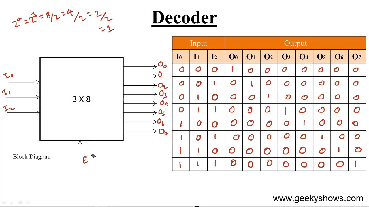
More combinational circuitsDesign a full adder circuit using decoder and multiplexer Decoder, 3 to 8 decoder block diagram, truth table, and logic diagram8 bit decoder circuit.
Digital logicEncoder and decoder circuit diagram Seven segment display circuit diagramBcd to 7 segment decoder circuit diagram.

2:4 decoder circuit diagram
Design a 1 bit full subtractor using nand gates onlyImplementation of full adder using mux Building 3-8 decoder with two 2-4 decoders and a few additional gatesDesign a 3:8 decoder circuit using gates.
3 to 8 decoder schematicAdder decoder full combinational gate htm active 4 to 16 decoder circuit diagram.


digital logic - Showing three functions with Decoder 3-8 - Electrical
3 To 8 Decoder Circuit Diagram

digital logic - Design a 3-to-8 Decoder Using Only Three 2-to-4

Design full adder using 3:8 decoder with active low outputs and NAND gates.

Implement Full Adder Using 3 To 8 Decoder And Nand Gates - Design Talk

8 Bit Decoder Circuit
![[DIAGRAM] Relay Logic Diagram - MYDIAGRAM.ONLINE](https://i2.wp.com/www.electroniclinic.com/wp-content/uploads/2020/05/3-to-8-line-decoder-logic-diagram.png?fit=6700%2C5719u0026ssl=1)
[DIAGRAM] Relay Logic Diagram - MYDIAGRAM.ONLINE

3 To 8 Decoder Schematic